 English
 中文简体
中文简体 عربى
عربى
Contact Us




founded in 2006, is an enterprise focusing on the R&D, manufacturing, and customization of non-standard bearings, high-precision bearings (import substitution), and bearing accessories and mechanical parts. With more than 30 years of technical design experience, FTM has earned an excellent reputation in the field of high-quality bearings. Our professional technical team provides domestic and foreign customers with high-quality bearing solutions in engineering machinery, textile machinery, and other fields.
News Directory
- 1. Industrial Rolling Element Selection Guide: Ball Bearings vs. Roller Bearings in Heavy Duty Manufacturing
- 2. Structural Classifications of Industrial Roller Bearings: Deep Technical Analysis of Cylindrical, Tapered, Spherical, and Needle Configurations
- 3. Advanced Material Engineering and Thermal Processing Technologies for High-End Precision Bearings
- 4. Tribological Management and Precision Seal Integrity in Adverse Manufacturing Environments
- 5. Root Cause Failure Analysis and Preventive Maintenance Strategies for Industrial Power Transmissions
- 6. Comprehensive Industrial FAQ
- What are the main design factors that dictate when to choose a roller bearing instead of a ball bearing?
- How do spherical roller bearings accommodate structural misalignment without binding?
- What is the difference between true brinelling and false brinelling failure modes?
- Why does electrical fluting occur in modern electric motor bearings, and how can it be prevented?
- When should an industrial system utilize oil circulation lubrication instead of standard grease?
- 7. Strategic Technical References
Author: FTM
Date: Jul 12, 2026
Roller & Ball Bearings Guide: Industrial Engineering & Selection Matrix
1. Industrial Rolling Element Selection Guide: Ball Bearings vs. Roller Bearings in Heavy Duty Manufacturing
Selecting the optimal rolling element configuration is a foundational engineering decision that directly impacts the structural integrity, rotational efficiency, and operating lifespan of industrial machinery. Manufacturing facilities and global procurement networks continuously analyze performance trade-offs between ball bearings and roller bearings to ensure mechanical systems survive harsh factory conditions. While both component types serve the exact same primary function—reducing rotational friction and supporting dynamic loads—their internal architectures establish completely different operational parameters.
The structural variance between these two families originates from the physical shape of the rolling element itself. Ball bearings utilize perfectly spherical hardened steel components positioned between matching inner and outer raceway rings. This spherical geometry creates point contact against the guide tracks. Conversely, roller bearings implement cylindrical, conical, or needle-shaped rolling elements, establishing line contact along the length of the internal raceway paths. Understanding how point contact versus line contact manages physical forces is vital for plant engineers designing gearboxes, electric motors, and material handling systems.
Contact Geometry and Mechanical Load Distribution
The mechanics of point contact limit the overall surface area available to absorb operational forces. When a radial load is applied to a deep groove ball bearing, the pressure concentrates on a minuscule, theoretical dot at the apex of each steel sphere. This localized concentration allows the bearing to achieve extremely low rolling resistance, rendering ball bearings highly efficient for high-speed mechanisms where thermal buildup must be minimized. However, excessive structural forces applied to a point contact zone can lead to localized material deformation, micro-fracturing, and premature fatigue.
Roller bearings overcome load limitations through line contact distribution. By spreading the incoming radial or axial forces across the full length of a cylinder or a tapered cone, the internal mechanical stress per unit area decreases dramatically. This structural distribution enables roller bearings to survive heavy equipment impacts, continuous high-tonnage pressure, and severe shock loads that would instantly fracture or dent a standard ball bearing. For procurement officers sourcing components for large-scale production setups, identifying the primary load profile—whether it is light and rapid or massive and slow—is the first step toward avoiding unexpected mechanical downtime.
Rotational Velocity and Thermal Thresholds
Rotational speed capacity represents the inverse trade-off of load distribution. Due to the minimal surface friction inherent in point contact, ball bearings excel at high angular velocities. They generate negligible heat even when operating at elevated revolutions per minute, making them the standard choice for precision high-speed CNC spindles, standard electric motors, and automated optical sensors. The lower torque required to initiate rotation in ball bearings directly translates into energy conservation for the overall drive system.
Roller bearings, by virtue of their broader line contact surfaces, generate higher frictional resistance during operation. This increased friction creates greater thermal energy at elevated speeds, necessitating robust lubrication systems, oil circulation cooling paths, or specialized synthetic greases to dissipate heat. If a cylindrical or tapered roller bearing is forced into an application exceeding its rated velocity threshold without proper thermal management, the rolling elements risk thermal expansion, structural seizure, and catastrophic mechanical breakdown.
| Engineering Parameter | Ball Bearing Specifications | Roller Bearing Specifications |
|---|---|---|
| Primary Contact Type | Point Contact (Spherical) | Line Contact (Cylindrical/Tapered) |
| Radial Load Capacity | Low to Moderate | Exceptionally High |
| Axial Load Capacity | Moderate (Deep Groove / Angular) | Heavy (Tapered / Spherical Shapes) |
| Rotational Speed Rating | Exceptionally High RPM | Moderate to Low RPM |
| Frictional Energy Loss | Minimal | Moderate |
| Shock Load Resistance | Susceptible to Brinelling | Exceptionally High Resistance |
| Angular Misalignment Tolerance | Low to Moderate | Low (Except Spherical Variations) |
2. Structural Classifications of Industrial Roller Bearings: Deep Technical Analysis of Cylindrical, Tapered, Spherical, and Needle Configurations
Industrial roller bearings are categorized into distinct structural configurations, each engineered to address specific load directions, alignment challenges, and spatial restrictions within factory equipment. Selecting the correct geometry requires a comprehensive evaluation of radial forces, thrust forces, and structural housing geometry.
Cylindrical Roller Bearings: Engineering Design and Velocity Boundaries
Cylindrical roller bearings are built with precision ground cylinders guided by integral ribs on either the inner or outer ring races. These components are uniquely suited for systems experiencing pure, heavy radial loads. Because the cylinders are free to slide axially between the retaining ribs on certain configurations, these bearings can accommodate axial thermal expansion of the drive shaft without binding the mechanical assembly.
The internal geometry of modern cylindrical rollers includes slightly crowned profiles near the outer edges of the cylinders. This subtle curvature prevents stress concentration at the corners, reducing the risk of edge loading failure when the shaft undergoes minor deflection under load. Cylindrical variants are frequently used in heavy-duty industrial gearboxes, paper mill machinery, and large pumps where high radial capacity must match moderate velocity requirements.
Tapered Roller Bearings: Managing Bi-Directional Combined Forces
Tapered roller bearings feature conical rolling elements guided by an inner ring cone and an outer ring cup. This angled design allows the component to support simultaneous combinations of massive radial and axial forces. The steepness of the cup angle determines the specific ratio of thrust load the bearing can support; a wider angle increases the axial load capacity, making it perfect for heavy industrial gearboxes and wheel hub assemblies.
Because of their asymmetrical geometry, single-row tapered roller bearings cannot support axial loads in both directions independently. They must be mounted in pairs, facing opposite directions, or configured as double-row pre-loaded assemblies to ensure complete shaft stabilization. This configuration provides high system rigidity, preventing shaft deflection in heavy mechanical presses, industrial rolling mills, and mining machinery.
Spherical Roller Bearings: Self-Aligning Mechanisms for Severe Environments
For severe applications involving heavy loads, structural deflections, and unavoidable shaft misalignments, spherical roller bearings are the standard industrial choice. These bearings feature two rows of barrel-shaped rollers running inside a common outer ring with a continuous spherical raceway surface. This configuration allows the inner ring assembly to tilt smoothly inside the outer ring without increasing friction or reducing operating life.
This self-aligning capability protects the bearing from premature failure caused by structural bending, frame flexing, or assembly misalignment. Spherical roller bearings are commonly installed in heavy continuous casting machinery, vibrating screens, industrial crushers, and marine propulsion shaft lines where extreme force is regularly accompanied by structural movement.
Needle Roller Bearings: Maximizing Radial Capacity in Confined Spaces
When radial space within a machine housing is limited, needle roller bearings provide a highly efficient solution. These bearings use long, thin cylindrical rollers with a length-to-diameter ratio exceeding four to one. Despite their minimal cross-sectional profile, the large collective surface area of the needle array delivers high radial load capacity within a very small footprint.
Needle bearings can be supplied with or without a dedicated inner ring. In configurations omitting the inner ring, the needle rollers run directly on the surface of the hardened and ground shaft itself, saving space. This makes them ideal for automotive transmissions, planetary gear train sets, and compact hydraulic pumps where overall component weight and volume must be minimized.
3. Advanced Material Engineering and Thermal Processing Technologies for High-End Precision Bearings
The operational lifespan and reliability of high-grade industrial bearings depend directly on the metallurgical composition and thermal processing methods used during manufacturing. As heavy industries demand components capable of surviving harsher operating environments, bearing manufacturers must utilize advanced metallurgy to prevent premature failure.
Metallurgical Compositions and High-Purity Clean Steel Alloys
The standard material for high-load industrial bearing components is high-carbon chromium steel, typically classified under global standards as AISI 52100 or 100Cr6. This alloy contains approximately 1% carbon and 1.5% chromium, providing an ideal balance of wear resistance, structural toughness, and uniform through-hardening capabilities. However, standard steel contains microscopic non-metallic inclusions, such as oxides and sulfides, which act as internal stress concentrators, potentially initiating subsurface fatigue cracks under heavy cyclic loads.
To maximize structural reliability, premium industrial bearings undergo advanced purification processes, including Vacuum Degassing (VD), Vacuum Arc Remelting (VAR), or Electro-Slag Remelting (ESR). These refining techniques eliminate dissolved gases and microscopic inclusions, resulting in ultra-clean steel alloys. Utilizing ultra-clean steel drastically extends the rolling contact fatigue life of the bearing, allowing components to survive millions of high-stress revolutions without structural degradation.
Carbonitriding and Heat Treatment Protocols
To survive environments contaminated by abrasive particles or suffering from marginal lubrication film thickness, bearing rings and rolling elements undergo precise thermal treatments. Through-hardening involves heating the components above the transformation temperature followed by an oil quench and tempering, ensuring uniform hardness throughout the cross-section.
For applications subject to extreme impact forces or heavy particulate contamination, carbonitriding is often preferred. This process diffuses carbon and nitrogen into the steel surface at elevated temperatures, followed by controlled quenching. The result is a highly wear-resistant surface layer with high compressive stresses, paired with a tough, ductile core. This surface layer resists scoring from abrasive dust while the core absorbs sudden shock loads without fracturing.
4. Tribological Management and Precision Seal Integrity in Adverse Manufacturing Environments
Proper lubrication and effective sealing systems are crucial for maximizing the service life of rolling element bearings. According to industrial maintenance data, more than a third of premature bearing failures result from improper lubrication management or contamination by external moisture and debris.
Lubrication Dynamics: Hydrodynamic Film and Viscosity Selection
Lubrication functions by forming a microscopic hydrodynamic film between the rolling elements and the raceway tracks. This film separates the metal surfaces, preventing direct contact and minimizing adhesive wear. The selection between industrial grease and circulating oil depends on the operating speed, ambient temperature, and load requirements of the application.
Grease is typically selected for standard industrial equipment due to its ease of retention and inherent sealing properties. It consists of a base oil held within a thickener matrix, such as lithium complex, polyurea, or calcium sulfonate. Oil lubrication is preferred for high-speed or high-temperature systems where continuous fluid circulation is required to carry heat away from the rotating assembly. Selecting the correct base oil viscosity is critical; if the viscosity is too low, the oil film will collapse under load, leading to metal-to-metal contact. Conversely, excessive viscosity increases internal fluid friction, raising operating temperatures and wasting energy.
Sealing Systems for Contamination Control
In harsh operating environments, such as cement production, mining, and agricultural processing, bearings must be protected against dust, mud, and water ingress. Sealing mechanisms are split into two primary categories: contact seals and non-contact seals.
- Contact Seals: These components utilize synthetic rubber or elastomer lips that press directly against the inner ring surface. They provide exceptional sealing performance against moisture and fine dust, but generate additional friction, which limits the maximum allowable speed of the bearing.
- Non-Contact Seals: These options, including metal shields and labyrinth seals, rely on complex, close-clearance gaps to block contaminants. Because there is no physical contact with the rotating elements, they generate zero friction, making them suitable for high-speed machinery. Labyrinth paths are often packed with grease to create a physical barrier against external particulates.
5. Root Cause Failure Analysis and Preventive Maintenance Strategies for Industrial Power Transmissions
To minimize unplanned downtime and optimize component life, maintenance teams must understand the physical mechanisms behind bearing degradation. Identifying failure modes early allows operators to implement targeted corrections before catastrophic damage occurs.
Identifying Failure Modes: Fatigue, Brinelling, and Electrical Erosion
- Surface Fatigue (Flaking): This represents the natural end of a bearing’s operational life, appearing as the spalling or flaking of metal particles from the raceways. However, if flaking occurs prematurely, it typically indicates chronic overloading, shaft misalignment, or inadequate lubrication film thickness.
- Brinelling (True and False): True brinelling consists of distinct indents spaced along the raceway, caused by extreme impact loads or incorrect installation forces that exceed the material’s elastic limit. False brinelling appears as elongated wear marks caused by micro-vibrations when the machine is stationary, wearing away the metal through fretting corrosion.
- Electrical Erosion (Fluting): In modern industrial setups utilizing Variable Frequency Drives (VFDs), stray electrical currents can travel down the motor shaft, passing through the bearing oil film. This results in microscopic electrical arcing, which creates parallel burn grooves, known as fluting, across the raceways. This damage causes loud acoustic noise and rapid structural failure.
Advanced Diagnostic Tools: Vibration Analysis and Acoustic Monitoring
Modern preventive maintenance programs rely on advanced diagnostic instruments to detect internal bearing faults long before visual damage occurs.
- Vibration Analysis: By placing accelerometers on the bearing housing, technicians track specific fault frequencies. Inner ring defects (BPFI), outer ring defects (BPFO), and rolling element defects (BSF) generate distinct frequency peaks. Monitoring these signal trends allows factories to schedule maintenance before structural failure occurs.
- Acoustic Emission Testing: High-frequency acoustic sensors detect stress waves generated by micro-cracks or microscopic friction within the bearing. This technology provides early warning of lubrication failure or contamination, allowing operators to regrease the component before surface damage begins.
6. Comprehensive Industrial FAQ
What are the main design factors that dictate when to choose a roller bearing instead of a ball bearing?
The choice depends primarily on the load profile, speed requirements, and space constraints of the application. Roller bearings should be selected when the system experiences heavy radial forces or severe shock loads, as their line contact geometry distributes stress over a larger surface area. Ball bearings are preferred for high-speed applications with light to moderate loads, where minimizing friction, heat generation, and starting torque is critical.
How do spherical roller bearings accommodate structural misalignment without binding?
Spherical roller bearings utilize two rows of barrel-shaped rollers that run inside an outer ring with a continuously curved, spherical internal raceway. This design allows the inner ring, cage, and roller assembly to tilt freely within the outer ring. As a result, the bearing can tolerate angular misalignment caused by shaft deflection or installation errors without increasing internal friction or reducing operational life.
What is the difference between true brinelling and false brinelling failure modes?
True brinelling is permanent plastic deformation of the raceway caused by a massive static overload or impact force, which leaves distinct indents corresponding to the shape of the rolling elements. False brinelling is a form of fretting wear caused by microscopic vibrations while the bearing is stationary. This wear displaces metal and rubs away the lubrication film, creating cavities that resemble brinelling but are actually caused by mechanical abrasion.
Why does electrical fluting occur in modern electric motor bearings, and how can it be prevented?
Electrical fluting occurs when stray currents from Variable Frequency Drives (VFDs) travel through the motor shaft and arc across the bearing’s lubrication film to reach the ground. This arcing creates a series of parallel burn marks or grooves across the raceway. It can be prevented by installing insulated ceramic bearings, using conductive grounding brushes on the shaft, or specifying hybrid bearings with non-conductive silicon nitride rolling elements.
When should an industrial system utilize oil circulation lubrication instead of standard grease?
Oil circulation lubrication should be used when the application operates at exceptionally high speeds or temperatures where grease would break down or shear excessively. Circulating oil continuously flows through the bearing, carrying away heat and filtering out wear debris. Grease is typically preferred for self-contained, low-to-moderate speed systems due to its ease of retention and simple maintenance requirements.
7. Strategic Technical References
- ISO 281: Rolling bearings — Dynamic load ratings and rating life. This international standard establishes the foundational formulas for calculating basic rating life based on fatigue conditions.
- ANSI/ABMA Standard 9: Load ratings and fatigue life for ball bearings, providing industry guidelines for structural rating calculations.
- ANSI/ABMA Standard 11: Load ratings and fatigue life for roller bearings, defining the official load performance metrics for cylindrical, tapered, and spherical variants.
- DIN 635-1: Rolling bearings; radial spherical roller bearings; single row, barrel bearings. This standard defines the dimensions, tolerances, and configurations for self-aligning barrel roller bearings.
- DIN 616: Rolling bearings; structural framework for dimensions, establishing the standard geometric boundaries and boundary sizes for international rolling bearing production lines.
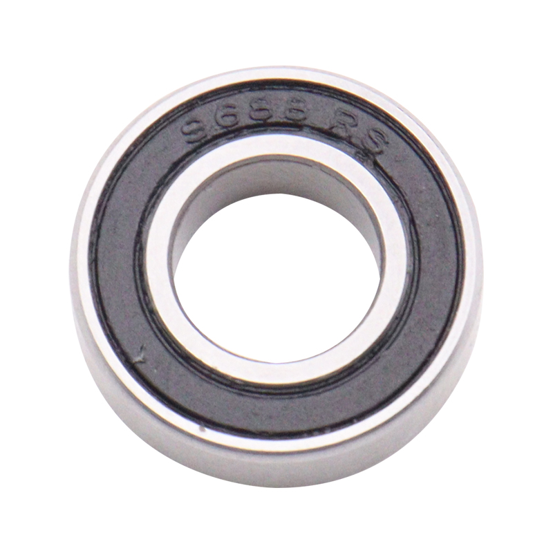
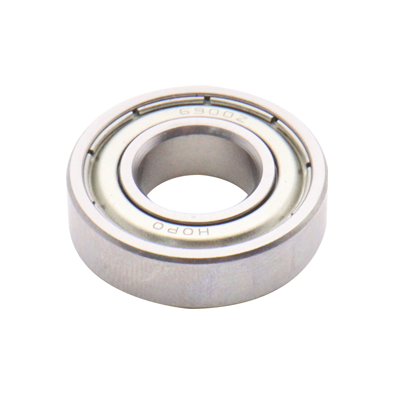
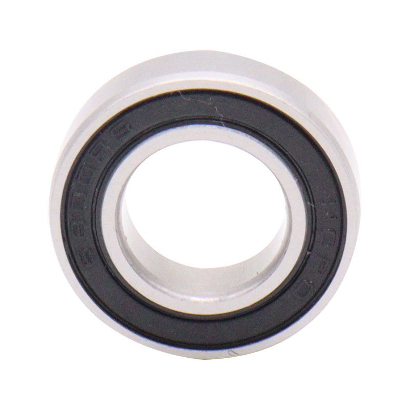
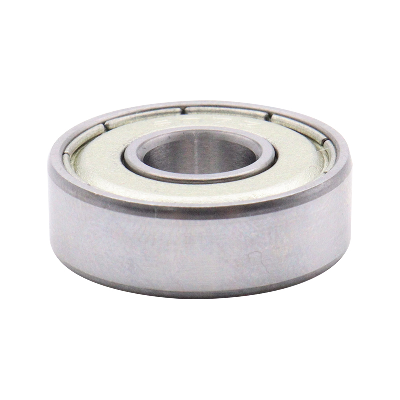
Selected Bearing Display

 Download Catalog
