 English
 中文简体
中文简体 عربى
عربى
Contact Us




founded in 2006, is an enterprise focusing on the R&D, manufacturing, and customization of non-standard bearings, high-precision bearings (import substitution), and bearing accessories and mechanical parts. With more than 30 years of technical design experience, FTM has earned an excellent reputation in the field of high-quality bearings. Our professional technical team provides domestic and foreign customers with high-quality bearing solutions in engineering machinery, textile machinery, and other fields.
News Directory
- 1. Introduction to Primary Ball Bearing Categories
- 2. Structural Design and Geometrical Variations
- 3. Load Carrying Capacity and Force Distribution
- 4. Operational Speed Limits and Precision Parameters
- 5. Industrial Arrangement Configurations and Mounting Methods
- 6. Real-World Application Environments and Use Cases
- 7. Comparative Performance Criteria Checklist
- 8. Summary of Selection Guidelines
- 9. Frequently Asked Questions
- 1. Can a deep groove ball bearing be replaced directly with an angular contact ball bearing?
- 2. Why do angular contact ball bearings require a preload during installation?
- 3. How can an operator identify the correct mounting direction for an angular contact bearing?
- 4. What are the primary indicators that a ball bearing is failing due to improper axial load allocation?
- 5. Do deep groove ball bearings require regular re-lubrication?
- 10. References
Author: FTM
Date: May 26, 2026
Deep Groove Ball Bearings vs Angular Contact Ball Bearings: The Complete Industrial Selection Guide
1. Introduction to Primary Ball Bearing Categories
In the field of mechanical power transmission, industrial machinery, and rotating equipment, components must be selected with high precision to ensure operational longevity. Among the wide array of rolling element designs, ball bearings remain the most widely utilized configuration across global industrial manufacturing. These components convert sliding friction into rolling friction by using spherical rolling elements maintained between specialized inner and outer rings.
While the fundamental concept of a rolling element remains uniform, the specific design architectures of individual categories differ significantly. These engineering variations heavily influence how loads are distributed, how high speeds are handled, and how long the component lasts in heavy industrial environments.
Among the various subcategories of industrial ball bearings, single row deep groove ball bearings and single row angular contact ball bearings are the two most essential styles found in modern manufacturing lines. Industrial procurement managers, technical buyers, and systems design engineers frequently must evaluate these two specific categories when establishing design parameters for new machinery or when selecting replacement components for critical factory maintenance.
Understanding the structural geometry, structural behaviors under variable loads, maximum rotational limits, and specific operational environments of each design is necessary to prevent premature mechanical breakdown and ensure uninterrupted production.
2. Structural Design and Geometrical Variations
To thoroughly understand why these two variations perform differently under stress, it is necessary to examine their internal geometry and physical construction. Both designs consist of four foundational parts: an inner ring, an outer ring, a complement of precision spherical balls, and a cage or retainer that keeps the balls evenly spaced. However, the exact configuration of the internal pathways, known as the raceways, is where the structural deviations occur.
Deep Groove Ball Bearing Geometry
The single row deep groove ball bearing features high, symmetrical shoulders on both sides of the raceway channels in both the inner and the outer rings. The groove forms a continuous, uninterrupted arc that closely matches the curvature radius of the spherical balls. This geometric layout creates a clear, centered path for the rolling elements.
Because both sides of the outer ring channel possess uniform shoulder heights, the balls are securely held within the deepest section of the raceways during standard operation. This symmetrical alignment provides high stability under simple operating conditions but restricts the shifting of the load line when force styles change.
Angular Contact Ball Bearing Geometry
In contrast, the angular contact ball bearing uses an asymmetrical structural layout. While the inner ring maintains a specialized configuration, the outer ring is manufactured with one shoulder significantly lower or cut away compared to the opposing side. This specific design creates a distinct, angled contact path between the balls and the raceway walls.
The line connecting the contact points of the ball and the raceways forms a distinct angle relative to a line drawn perpendicular to the bearing shaft axis. This angle is standardly engineered at fixed positions such as 15 degrees, 25 degrees, or 40 degrees, depending on the specific application needs. A larger contact angle enables the bearing to support much greater axial forces, though it alters how the bearing must be oriented during installation.
Structural Comparison Matrix
The table below outlines the core differences in the physical layout and architecture of these two industrial components:
| Design Feature | Deep Groove Ball Bearings | Angular Contact Ball Bearings |
|---|---|---|
| Outer Ring Symmetry | Completely symmetrical with uniform double shoulders | Asymmetrical with one high shoulder and one relieved shoulder |
| Raceway Grooves | Continuous, deep concentric channels on both rings | Offset channels designed to support angled load pathways |
| Contact Angle | Nominally zero degrees under zero external load | Fixed angles standardly at 15, 25, or 40 degrees |
| Ball Complement | Standard ball count based on filling slots or cage style | High ball count optimized for specific thrust load pathways |
| Cage Configurations | Pressed steel, molded polyamide, or machined brass | Machined brass, reinforced polyamide, or phenolic resin |
3. Load Carrying Capacity and Force Distribution
The structural variances between these two types directly dictate how forces are distributed through the component during active machine runtime. Mechanical loads are generally divided into two main vector orientations: radial loads, which apply force perpendicular to the rotating shaft, and axial loads, which apply force parallel to the centerline of the shaft.
Radial and Axial Load Dynamics
Deep groove designs are optimized primarily for supporting heavy radial loads. Because the spherical balls roll smoothly in the center of the deep concentric grooves, radial forces pass straight through the vertical centerline of the component. However, because the side shoulders are tall and continuous, these components can also handle a moderate amount of axial load in either direction.
When an axial force hits a deep groove component, the balls shift slightly up the side of the raceway groove, creating a small, temporary contact angle. This flexibility makes them highly versatile for basic machinery where minor shaft shifting occurs, though excessive axial stress will accelerate wear.
Angular contact designs are engineered to handle combined loads, which consist of major radial and major axial forces acting simultaneously. Because of the built-in, fixed contact angle, an applied radial force creates an internal axial force that must be countered. Consequently, a single row angular contact component cannot operate without a corresponding thrust load or an opposing bearing to balance the force vector.
These components can support exceptionally high axial loads, but strictly in one direction. If an axial force is applied from the wrong direction, it pushes the balls toward the relieved, lower shoulder of the outer ring, causing rapid tracking errors, severe heat generation, and immediate mechanical failure.
4. Operational Speed Limits and Precision Parameters
Rotational velocity limitations and dimensional precision standard adherence are critical metrics when specifying components for automated manufacturing infrastructure and high-speed processing machinery.
Rotational Velocity Capabilities
The maximum allowable speed of a rolling element component depends heavily on internal friction generation, lubrication retention, and cage stability. Deep groove ball bearings are known for generating very low friction during standard operation. The centered, minimal contact zone of the balls within the symmetrical tracks keeps torque requirements low and prevents rapid temperature spikes. This allows them to run at high velocities in grease-lubricated or oil-lubricated environments, particularly when fitted with lightweight pressed steel or synthetic cages.
Angular contact variants are also capable of running at high rotational velocities, and in specific setups, they can exceed the speed limits of deep groove designs. High-precision angular contact components utilized in machine tool spindles are manufactured to strict accuracy standards.
The constant contact between the balls and the angled raceways prevents ball sliding or skidding, which can occur in deep groove setups under variable forces. When equipped with lightweight, high-rigidity phenolic resin or machined synthetic cages, angular contact setups can maintain stability at exceptionally high RPM levels.
Precision Classification Standards
Industrial ball bearings are manufactured according to standard precision tolerance classes established by global standardization bodies. These ratings govern the allowable variations in outer dimensions, inner bore roundness, and radial running accuracy.
Deep groove components are widely manufactured across standard baseline precision levels for general industrial applications, though high-precision grades are available for specialty equipment. Angular contact components are regularly manufactured to high-precision tolerance specifications, as they are frequently deployed in systems where tiny shaft deviations or positional variations cannot be tolerated.
5. Industrial Arrangement Configurations and Mounting Methods
Because single-row angular contact designs can only support thrust forces in a single direction, they require unique mounting methods that are rarely necessary when deploying standard deep groove components.
Deep Groove Installation Methods
Installing a deep groove ball bearing is straightforward. Because the component is structurally self-retaining and symmetrical, it can be mounted onto a shaft and into a housing without regard to directional orientation. It can handle minor bidirectional thrust loads autonomously. In standard machinery setups, a single deep groove component can serve as the locating bearing on a shaft, pinning it axially within the housing, while a second bearing allows for thermal expansion on the opposite end.
Angular Contact Pairing Systems
A single row angular contact component is rarely used alone. To handle bidirectional thrust forces or to maintain shaft rigidity under heavy radial stress, these bearings are mounted in pairs or complex multi-bearing sets. When manufacturing plants order these components, they frequently choose universally matchable bearings that can be arranged in three primary setups:
- Face-to-Face Arrangement: The front faces of the outer rings are positioned next to each other. The load lines converge toward the bearing axis. This arrangement is highly effective at handling combined forces while allowing for a slight degree of housing misalignment or structural flexing.
- Back-to-Back Arrangement: The back faces of the outer rings are placed together. The load lines diverge away from the bearing shaft axis, creating a wide effective distance between the support centers. This configuration provides high structural rigidity and offers exceptional resistance to tipping forces or moment loads.
- Tangent or Tandem Arrangement: The bearings are mounted in a parallel orientation, facing the same direction. This allows the axial load to be shared equally across both units, doubling the thrust handling capability in that single direction. An opposing bearing or set is still required on the far end of the shaft to lock the system into position.
6. Real-World Application Environments and Use Cases
The distinct structural attributes of these two bearing classes dictate their placement within modern manufacturing facilities, industrial processing units, and consumer goods.
Common Deep Groove Applications
Deep groove components are the standard choice for general-purpose machinery that requires reliable operation, low maintenance, and cost efficiency. They are widely utilized in electric motors, where low noise, low friction, and high speeds are necessary.
They are also found in domestic appliances, ventilation fans, centrifugal water pumps, and industrial conveyors. Because these bearings are available in pre-lubricated, double-sealed configurations, they can operate for years inside enclosed machinery without requiring manual grease replenishment.
Common Angular Contact Applications
Angular contact components are preferred for heavy-duty, high-precision industrial applications where shafts are subjected to severe thrust forces or require rigid axial positioning. A premier example is the CNC machine tool industry, where milling and turning spindles must maintain precise positioning under cutting loads.
They are also widely deployed in multi-stage high-pressure centrifugal pumps, vertical deep-well pumps, industrial gearboxes, and automotive transaxles. Additionally, heavy manufacturing equipment such as screw compressors and metal extrusion lines relies on matched sets of angular contact bearings to handle the immense continuous axial pressures generated during product processing.
7. Comparative Performance Criteria Checklist
When choosing between these two major bearing types for equipment design or facility replacement strategies, engineering teams should evaluate specific operational variables. The following checklist highlights how each category handles critical performance metrics:
- Radial Load Superiority: Deep groove designs provide excellent radial support in simple single-bearing configurations.
- Axial Load Efficiency: Angular contact designs handle high, single-direction thrust forces efficiently through specialized contact angles.
- Bidirectional Thrust Flexibility: Deep groove bearings accept light axial forces from both directions without requiring pairs.
- System Rigidity and Deflection Minimization: Back-to-back angular contact pairs minimize shaft deflection and eliminate mechanical play.
- Maintenance Simplicity: Sealed deep groove variants operate as sealed-for-life units, lowering manual maintenance needs.
- Initial Procurement Economics: Deep groove bearings are highly cost-effective due to high-volume global production lines.
8. Summary of Selection Guidelines
Choosing the proper ball bearing is a balance of performance capability, system geometry, and long-term operating costs. Deep groove ball bearings provide versatile, cost-effective, and low-maintenance operation for machinery focused on radial loads and high-speed operation. Their ability to handle minor bidirectional thrust forces without complex mounting arrangements makes them an ideal choice for standard motors, pumps, and general industrial equipment.
When machinery demands high precision, faces combined radial and axial loads, or requires rigid shaft tracking under high operational forces, angular contact ball bearings become necessary. Though they require precise directional orientation and are typically mounted in matched pairs, their ability to handle heavy thrust forces ensures structural integrity in demanding environments like machine spindles and heavy-duty gearboxes. By matching these bearing characteristics to the specific requirements of your industrial application, you can achieve optimal service life and prevent unexpected equipment downtime.
9. Frequently Asked Questions
1. Can a deep groove ball bearing be replaced directly with an angular contact ball bearing?
No, a direct one-to-one replacement is generally not possible without altering the system configuration. Single row angular contact ball bearings require a constant axial load or an opposing bearing to balance internal forces. Replacing a single deep groove bearing with a single angular contact bearing will cause the component to separate or fail rapidly if thrust forces shift or if radial loads act alone.
2. Why do angular contact ball bearings require a preload during installation?
Preloading involves applying a permanent axial force to the bearing set during installation. This step ensures continuous contact between the spherical balls and the raceway tracks, eliminating internal clearances, preventing ball skidding at high speeds, and increasing the overall rigidity of the shaft assembly.
3. How can an operator identify the correct mounting direction for an angular contact bearing?
The outer rings of angular contact bearings are manufactured with asymmetric faces, showing a thick side and a thin side. Manufacturers mark the outer ring surfaces with specific indicators or V-shaped lines to show how the load pathways align. The thick shoulder face must always be oriented to receive the incoming axial thrust force.
4. What are the primary indicators that a ball bearing is failing due to improper axial load allocation?
When a deep groove bearing is overloaded axially, it exhibits a tracking line shifted high up on the raceway walls, accompanied by increased operating noise and a rapid rise in housing temperature. For an angular contact bearing loaded from the wrong direction, symptoms include rapid cage deformation, metallic debris in the grease, and immediate lockup due to the balls overriding the lower shoulder.
5. Do deep groove ball bearings require regular re-lubrication?
It depends on the enclosure style. Deep groove bearings specified with rubber seals or steel shields are packed with an optimized volume of industrial grease during production and are designed to be maintenance-free for life. Open variants lack integrated seals and require regular lubrication via grease nipples or an oil bath system.
10. References
- ISO 15: Rolling bearings — Radial bearings — Boundary dimensions, general plan. International Organization for Standardization.
- ANSI/ABMA Std 9: Load Ratings and Fatigue Life for Ball Bearings. American Bearing Manufacturers Association.
- Harris, T. A., & Kotzalas, M. N. (2006). Essential Concepts of Bearing Technology (5th ed.). CRC Press.
- Eschmann, P., Hasbargen, L., & Weigand, K. (1985). Ball and Roller Bearings: Theory, Design, and Application. John Wiley & Sons.
- Industrial Lubrication and Tribology Handbook. Volume 2: Standard Rolling Element Engineering Principles.
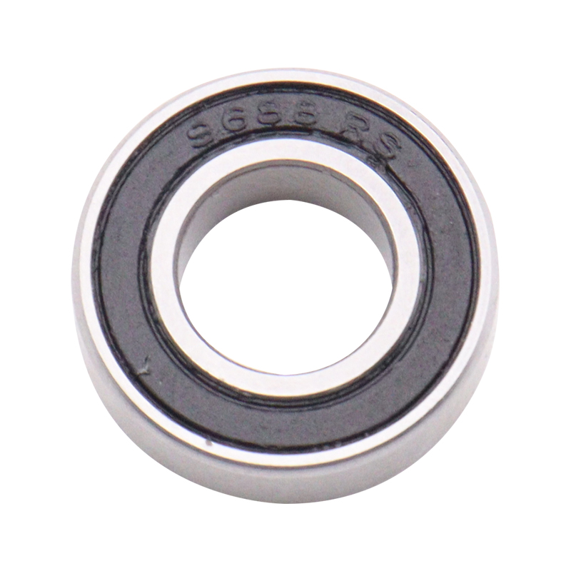
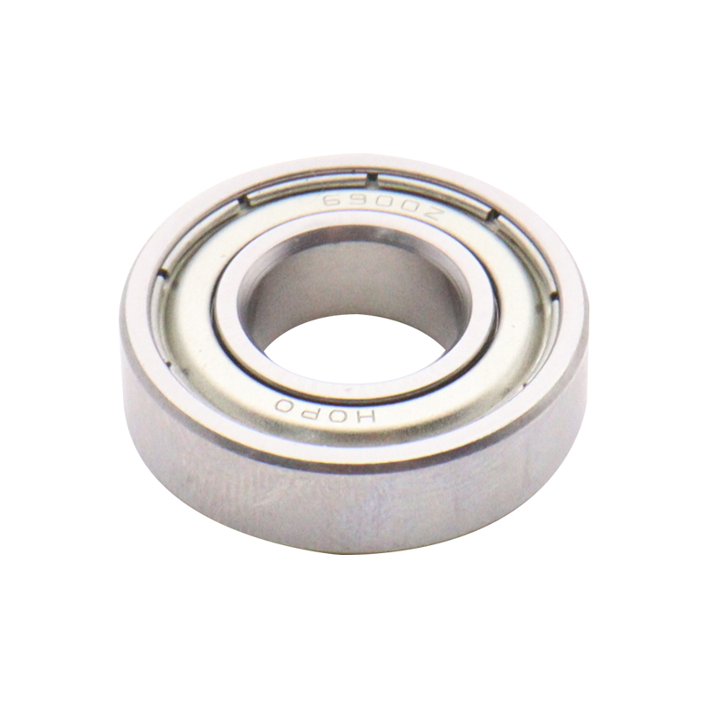
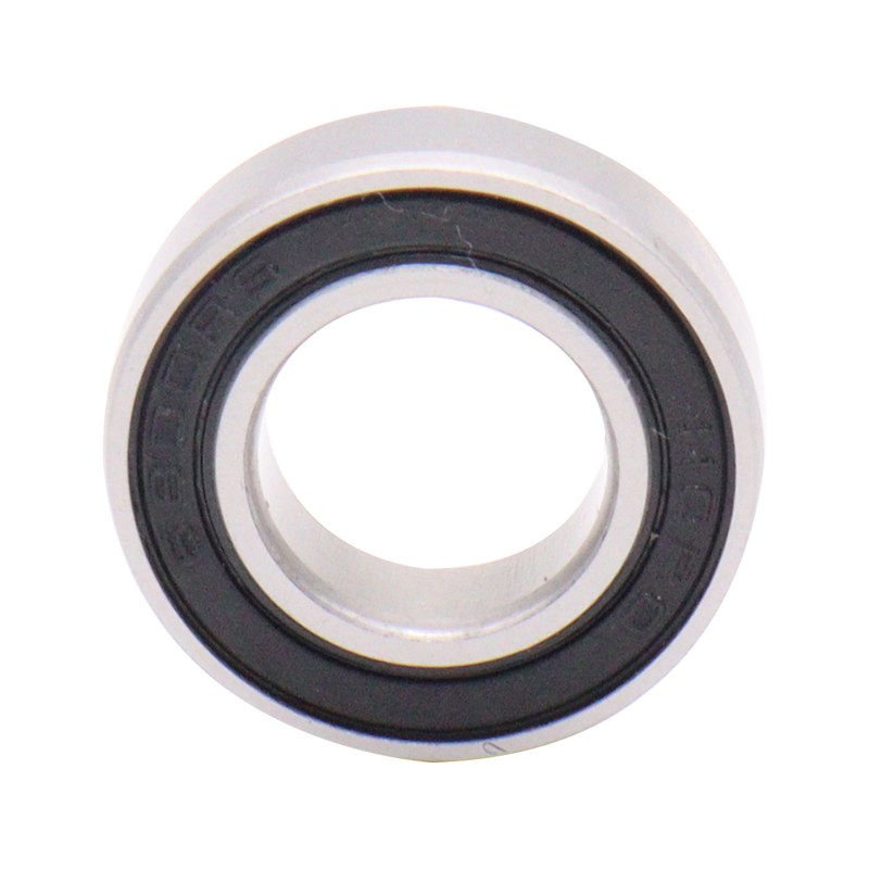
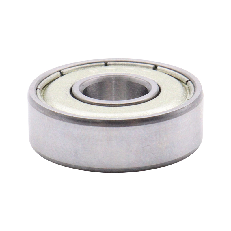
Selected Bearing Display

 Download Catalog
